|
|
|
| Product classification
> Mag, Vortex flowmeter & etc >
EMF
Series |
| EMF
Series |

|
|
|
|
|
|
|
| No
|
Model
Name
|
PDF
Download
|
| Catalog
| English
Operating Manual
|
| 1
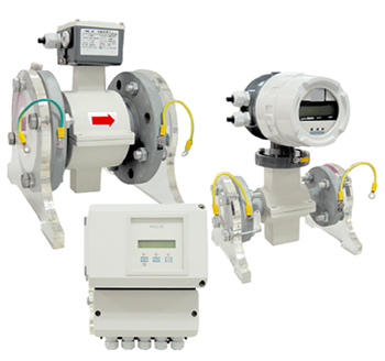
| Electromagnetic flow
meter
(EMF Series) |
 Download[605.0
KB] Download[605.0
KB] | Download
[2106 KB] |
|
|
|
|
| |
|
|
 Product
Feature Product
Feature
|
•
Wide size
applications. Available size connection 3mm to 1000mm.
•
Products
are the ideal flowmeters for metering the flow of all
liquids, slurries and sludges that have a
specific
minimum electrical conductivity.
•
Create no
additional pressure drop.
•
Contain
no moving or protruding parts, are wear free and corrosion
resistant.
•
Installations
are possible in any existing piping system.
•
Output
available both of current output and pulse output. (RS-485
Options)
|
|
|
|
| |
|
|
| Product
Application
|
•
Sewage
disposal plant
|
•
Paper and
Pulp manufacture
|
•
Food
manufacture(Beer,Milk,Juice)
|
•
Power
plant
|
•
Cooling
circulation water
|
•
Sea water
|
•
Steel
manufacture
|
•
Petrochemical
manufacture
|
|
|
|
| |
|
|
| Product
Description
|
ientek
of Electromagnetic Flowmeters(EMF) can be used to accurately
measure the flowrate of liquids,
paper
pulp, slurry and mineral slurry which has an electrical
conductivity greater than 5μS/cm.
EMFF
Integral Type is a flow measurement system in a compact
design which integrates the primary and
signal converter.
EMFS
Remote Type flow measurement system consists of a flowmeter
primary and a remote mounted converter.
The Faraday Laws of Induction, which state
that an induced electromotive force is generated in a
conductor when it moves through a magnetic
field, form the basis for the electromagnetic flowmeter
measurements.
This
measurement principle is applied to a conductive fluid which
flows in a pipe in which a magnetic
field is generated perpendicular to the
flow direction.
The electromotive force
which is induced in the fluid is measured at two electrodes
located diametrically
opposite to each
other.
This signal voltage UE is
proportional to the magnetic induction B, the electrode
spacing D and the
average fluid velocity
v.
Since the magnetic induction B and the
electrode spacing D are constant values the signal voltage
UE is
proportional to the average fluid
velocity v.
The equation for calculating
the volumetric flowrate shows that the signal voltage UE is
linear and
proportional to the average
fluid velocity v.
The induced signal
voltage is converted into programmable analog and digital
output signals in the converter.
|
|

|
 |
|
|
|